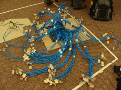
I want to take a few moments to talk about Peggy. I spent most of my life for two weeks soldering LEDs to pixel boards, ethernet cables to pixel boards, and ethernet cable to the main LED board. Then we discovered that the board didn't behave the way it was supposed to. Entire sections of the board weren't lighting up the LEDs, and the ones that did were not behaving in the manner they were supposed to.
So?
We spent ~$260, we were dead set on making Peggy do her job. We separated the cables into groupings of rows from top to bottom.
Peggy looked like a terrifying creating creature from the deepest and coldest crevices of the sea floor.
Turns out it was still far too difficult to understand what was happening on the board, Rachel and I tested pixels through the board, and began mapping out which LEDs worked, where connections were poor, and just trying to get a general idea of where things were going wrong. Then Z said the forums discouraged our method, and asked that we put up the LEDs in the same mapping as the board itself. So we did, for two hours.
Peggy gets more and more intimidating with every moment. We ordered a chip replacement kit, but we discovered the damage was in the board itself, the causes are a little uncertain, but may have had something to do with chips being put in in the reverse locations as where they should have been.
So Eric came up with a brilliant plan- replace Peggy with copper tape, some transistors, and wire up the LEDs so we light up all of the LEDs of one color at a time, instead of the intelligent pixels we had hoped for.
So, we put it together, some copper tape, some wires, and a handful of transistors
We held it together with my handy electrical tape.
And hated Peggy plan B just as much as Peggy. But, she worked!


No comments:
Post a Comment