Sunday, November 29, 2009

I spent five hours designing and all I got was this lousy t-shirt?

Man, a t-shirt for this class would be almost totally awesome.

Here's my utterly belated blog post.  Two weeks ago Eric and I spent some interesting hours trying to get adobe illustrator to make us a gear with the right diameter with teeth that didn't overlap, or drift off of the perimeter of the circle, or leave giant gaps in between each tooth.  To say the least, it was a particularly difficult task for the two of us.

Eric was just super excited that our latest degree of rotation attempt was unsuccessful.  Super excited.

To put our motor into the frame, Eric and I talked about Placing the motor at one extreme end of the frame, using an attachment to fix a 1/4" diameter, stainless steel rod to the motor, and using this self lubricating plastic (the name of which I've forgotten on three different occasions, this very moment included) to stabilize and attach the rod to the frame.  Small gears would be welded to the rod, we figured that two of these small gears, unless in testing we discover we need a third, would be sufficient points of contact for the gears on the mobile plane.  The motor would rotate the rod and the small gears, forcing the second plane, and the half gears attached to the second plane, to rotate.  This would give us the articulation we need in each of the five joints.

Our motor drivers were not handled with care. Crushed capacitors do not a motor driver make.  Fortunately the company sent us new ones almost lickity split.  Unfortunately one of the dual driver boards does not work at all.  Hopefully we can find a way to replace or repair it!

One of the planes of our lovely frame!  Good work team welding!

Perfectly sized for the motors and mounting.

Instead of just having some gears floating around as our gear prototype, Eric suggested scoring the cross section onto acrylic and using the motor and gears on the acrylic to show how the gears fit into the system.

I think it's quite lovely.

Watching the milling machine make our LED pixel boards (each small board accomodates 4 LEDs, red, green, blue, and white, which creates a pixel), was probably one of the more exciting things for me in this project. I soldered our LED control board, and when the small circuit boards were finally finished, Eric and I spent some hours soldering LEDs onto the boards, and testing them.  All in all a pretty fun day/evening (4pm-1am), listening to music, soldering, watching movies, soldering, more movies, testing boards, and soldering.  I love that I get to play around with things that you'd typically see in an eecs robotics design class, definitely not a materials science senior design.


So cool!


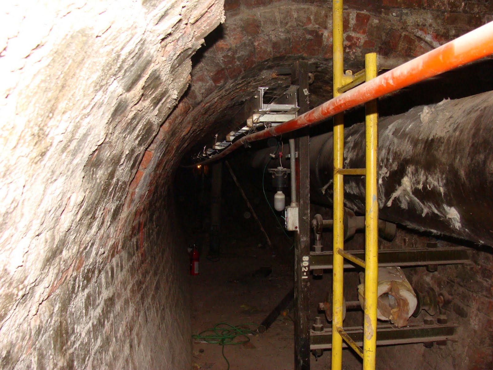
Just for fun I thought I'd include a picture of my adventure into the steam tunnels of an area and school that will remain unnamed.  I should probably remain mum as to how I got into them, but it's safe to say I went from one end of central to the extreme other end, without ever leaving these tunnels.

It was awesome!

Being productive in every way


Our group determined that our purposes would be best met by eliminating the sit "function" of the object, something I was very relieved about, I wasn't interested in desiging a chair that tries to feel me up.


Prototyping the actual size of the object, it would be 6ft tall if measured from ground to the tip of the "nose", just a little taller than Rachel!

Working with stepper motors to create the joint movement system

A prototype gear and assembly, Eric designed a model that creates two 3D planes to practice the hinge articulation. When she came, Michelle was very interested in seeing how we'd designed the movement of the planes

     Assembling the planes and the gear
The finished prototype assembly, I love putting motors in acrylic boxes, everything works and seeing the mechanical system through the container is really quit thrilling!
 This is how Eric determined the proportions of the gear system, he created, to scale, the cross-section of each object and overlayed them to create an accurate overview of the system. It's a very clever and intelligent way to go about designing things!
I learned how to use Rhino a bit in creating a model of this alternative hinge, Eric and I thought that a specially designed hinge would be a good choice for our system, it would allow us to easily insert our motor and gears into the frame and would make it possible for us to hide all gearing and attachements inside the frame.

Wednesday, November 4, 2009

Some more adventures in design

I started writing this post on Thursday, October 29th.  I am just now finishing it, sorry for the delay!

This morning we met to finalize our budget, and to bring together the assignments we'd been working on since our last meeting on Tuesday, which included building a fullsized model of the object shape, writing the budget paper, assembling a table of the desired and required components, calculating solar panel power and charge rate values, and physical system assembly requirements.


 The awkward family photo

While we met to finalize the task for this week, we also began with a discussion of our working values.  The last time we had met there was a clear divide in the group.  Half that didn't feel that the objective of the project required considerations for powering the system with solar energy, that the sustainability of the object would come in a social form.  The other half, however, felt that not focusing on solar energy as our power source was negating the whole objective of the course, which, as was infered, to create innovative systems that exemplify the "think green" mantra that has been attached to anything oriented around solar energy.

We recognized that we had fallen into a dangerous place, our group dynamic post-Tuesday meeting was not condusive to accomplishing anything. We discussed where we had had a breakdown. In our discussion there was even disagreement as to what had happened, and we realized that, while we talk a great deal in our meetings, when a disenting (differing) opinion was offered, there was not a strong argument given for the opinion. We all agreed that in the future we would all take an additive criticism approach. Instead of saying "No, I don't like it," we learned it was more productive, and fruitful, to say what we didn't agree with, give solid reasoning for our opinion, and a suggestion for a change or improvement to solve the problem.


I played around with the shape of the "chair" and how we could potentially install the different sensors and smart components.


Basic structure and form of the chair

Articulation of some of the hinges

More articulation of the chair.

We figured it would be easiest to have sun exposure on the solar panels if we placed them on the backside of the seat. I also explored the idea of having an LED display on the main face of the seat, which really only serves an interactive function if someone isn't sitting.


The back of the seat would pivot to orient itself for optimal sun exposure, it would also fold down toward the seat for high noon exposure