Saturday, December 19, 2009

Finally Finished

At 6 in morning, after having gotten breakfast at McDonald's, and not having gone to bed yet, we finished with peggy plan b, brought Simon over, and marveled in our craft.


Rachel still fit perfectly in his cold metallic arms.


So after having had slept for a couple hours, we rejoined forces to finish putting Simon together, and to install him in all of his glory in the gallery.  John took this picture, and I still feel like we build a sacrificial alien alter.  I don't see the correlation between this, and the robotic creature we intended to make people happy with.


In presentation, Simon did not move, had a limited color mixing display on his belly, didn't talk, didn't nod, didn't tweet, didn't make you warm, didn't harvest energy from the sun, didn't nothin.

Basically Simon was our dumbsurface, our "Downs Surface" as Eric liked to say.  He was far more complex than we could have ever guessed, especially when it came down to trying to get the camera to talk to the motors or the aruino, and fighting with Peggy for days.  I think we're fortunate it didn't collapse under it's own weight, the steel brackets Eric put in (I helped) really made a difference on the stability front.


When we presented, one of our guests, who was more than skeptical of all of the projects, and voiced his skepticism quite thoroughly, pointed out that our surface did essentially nothing, and he would never consider our project a success.  While I agree, in what we set out to do, we really didn't accomplish any of "Sustainability for happiness" goals, but the project wasn't a waste of time and money.  I didn't sleep three hours a night for three weeks, and struggle to keep up in my other classes because I was focusing almost singly on this project, to not feel like something was gained.

We made a 6 foot tall robot, who, until five minutes before we presented, did in fact move.  For proof, please view this video.  Rachel and I were definitely making embarrassingly excited noises


Peggy just would not cooperate

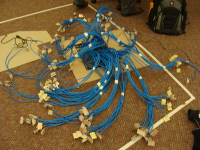
I want to take a few moments to talk about Peggy. I spent most of my life for two weeks soldering LEDs to pixel boards, ethernet cables to pixel boards, and ethernet cable to the main LED board.  Then we discovered that the board didn't behave the way it was supposed to.  Entire sections of the board weren't lighting up the LEDs, and the ones that did were not behaving in the manner they were supposed to.

So?


We spent ~$260, we were dead set on making Peggy do her job.  We separated the cables into groupings of rows from top to bottom.


Peggy looked like a terrifying creating creature from the deepest and coldest crevices of the sea floor.


Turns out it was still far too difficult to understand what was happening on the board, Rachel and I tested pixels through the board, and began mapping out which LEDs worked, where connections were poor, and just trying to get a general idea of where things were going wrong.  Then Z said the forums discouraged our method, and asked that we put up the LEDs in the same mapping as the board itself.  So we did, for two hours.

Peggy gets more and more intimidating with every moment.  We ordered a chip replacement kit, but we discovered the damage was in the board itself, the causes are a little uncertain, but may have had something to do with chips being put in in the reverse locations as where they should have been.

So Eric came up with a brilliant plan- replace Peggy with copper tape, some transistors, and wire up the LEDs so we light up all of the LEDs of one color at a time, instead of the intelligent pixels we had hoped for.


So, we put it together, some copper tape, some wires, and a handful of transistors


We held it together with my handy electrical tape.


And hated Peggy plan B just as  much as Peggy.  But, she worked!

Gears gears gear gears

In order to make Simon move, Eric and I had to make sure that the drive system we (mostly him, I'm terrible at these things, I think I was more company than helpful) designed actually worked.


After the gears were water jetted and welded to the brackets, or put onto the driveshaft, we realized something terrible had happened.

None of the gears meshed


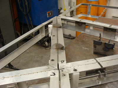
You can clearly see how far apart the gears are.  As it turns out, regardless of how perfect your digital simulation/design is, the physical manifestation of your system will not be perfect, especially when a majority of the dimensions are determined by the human factor constructing it.

So we have to start over.  The gears were re-cut, this time excluding the tabs Eric had designed to help keep the gears  securely in the steel brackets (there was no way we were going to try to weld steel to aluminum).


Once the gears were re-cut, we started preparing the frame for installation and manipulation of the gearing.


After hours and hours of reseating, grinding, fidgeting, and more grinding, we got each of the gears to mesh.


Then we welded everything in place, and by we, I mean Eric.  I learned how to MIG (Mig?) weld, but, as you can tell, my welding still needs a lot of practice.


I did have some good seams though! if you look closely you can see the two thin steel sheets look pretty nice in a few areas, and one of the four scrap gears I welded onto the thin sheets has four lovely welds, clean seams, basically everything this picture isn't.


We put that system in.


We welded that.


We made that motor flip that arm

We made Simon go, because we are rockstars

Sunday, November 29, 2009

I spent five hours designing and all I got was this lousy t-shirt?

Man, a t-shirt for this class would be almost totally awesome.

Here's my utterly belated blog post.  Two weeks ago Eric and I spent some interesting hours trying to get adobe illustrator to make us a gear with the right diameter with teeth that didn't overlap, or drift off of the perimeter of the circle, or leave giant gaps in between each tooth.  To say the least, it was a particularly difficult task for the two of us.

Eric was just super excited that our latest degree of rotation attempt was unsuccessful.  Super excited.

To put our motor into the frame, Eric and I talked about Placing the motor at one extreme end of the frame, using an attachment to fix a 1/4" diameter, stainless steel rod to the motor, and using this self lubricating plastic (the name of which I've forgotten on three different occasions, this very moment included) to stabilize and attach the rod to the frame.  Small gears would be welded to the rod, we figured that two of these small gears, unless in testing we discover we need a third, would be sufficient points of contact for the gears on the mobile plane.  The motor would rotate the rod and the small gears, forcing the second plane, and the half gears attached to the second plane, to rotate.  This would give us the articulation we need in each of the five joints.

Our motor drivers were not handled with care. Crushed capacitors do not a motor driver make.  Fortunately the company sent us new ones almost lickity split.  Unfortunately one of the dual driver boards does not work at all.  Hopefully we can find a way to replace or repair it!

One of the planes of our lovely frame!  Good work team welding!

Perfectly sized for the motors and mounting.

Instead of just having some gears floating around as our gear prototype, Eric suggested scoring the cross section onto acrylic and using the motor and gears on the acrylic to show how the gears fit into the system.

I think it's quite lovely.

Watching the milling machine make our LED pixel boards (each small board accomodates 4 LEDs, red, green, blue, and white, which creates a pixel), was probably one of the more exciting things for me in this project. I soldered our LED control board, and when the small circuit boards were finally finished, Eric and I spent some hours soldering LEDs onto the boards, and testing them.  All in all a pretty fun day/evening (4pm-1am), listening to music, soldering, watching movies, soldering, more movies, testing boards, and soldering.  I love that I get to play around with things that you'd typically see in an eecs robotics design class, definitely not a materials science senior design.


So cool!


Just for fun I thought I'd include a picture of my adventure into the steam tunnels of an area and school that will remain unnamed.  I should probably remain mum as to how I got into them, but it's safe to say I went from one end of central to the extreme other end, without ever leaving these tunnels.

It was awesome!

Being productive in every way


Our group determined that our purposes would be best met by eliminating the sit "function" of the object, something I was very relieved about, I wasn't interested in desiging a chair that tries to feel me up.


Prototyping the actual size of the object, it would be 6ft tall if measured from ground to the tip of the "nose", just a little taller than Rachel!

Working with stepper motors to create the joint movement system

A prototype gear and assembly, Eric designed a model that creates two 3D planes to practice the hinge articulation. When she came, Michelle was very interested in seeing how we'd designed the movement of the planes

     Assembling the planes and the gear
The finished prototype assembly, I love putting motors in acrylic boxes, everything works and seeing the mechanical system through the container is really quit thrilling!
 This is how Eric determined the proportions of the gear system, he created, to scale, the cross-section of each object and overlayed them to create an accurate overview of the system. It's a very clever and intelligent way to go about designing things!
I learned how to use Rhino a bit in creating a model of this alternative hinge, Eric and I thought that a specially designed hinge would be a good choice for our system, it would allow us to easily insert our motor and gears into the frame and would make it possible for us to hide all gearing and attachements inside the frame.

Wednesday, November 4, 2009

Some more adventures in design

I started writing this post on Thursday, October 29th.  I am just now finishing it, sorry for the delay!

This morning we met to finalize our budget, and to bring together the assignments we'd been working on since our last meeting on Tuesday, which included building a fullsized model of the object shape, writing the budget paper, assembling a table of the desired and required components, calculating solar panel power and charge rate values, and physical system assembly requirements.


 The awkward family photo

While we met to finalize the task for this week, we also began with a discussion of our working values.  The last time we had met there was a clear divide in the group.  Half that didn't feel that the objective of the project required considerations for powering the system with solar energy, that the sustainability of the object would come in a social form.  The other half, however, felt that not focusing on solar energy as our power source was negating the whole objective of the course, which, as was infered, to create innovative systems that exemplify the "think green" mantra that has been attached to anything oriented around solar energy.

We recognized that we had fallen into a dangerous place, our group dynamic post-Tuesday meeting was not condusive to accomplishing anything. We discussed where we had had a breakdown. In our discussion there was even disagreement as to what had happened, and we realized that, while we talk a great deal in our meetings, when a disenting (differing) opinion was offered, there was not a strong argument given for the opinion. We all agreed that in the future we would all take an additive criticism approach. Instead of saying "No, I don't like it," we learned it was more productive, and fruitful, to say what we didn't agree with, give solid reasoning for our opinion, and a suggestion for a change or improvement to solve the problem.


I played around with the shape of the "chair" and how we could potentially install the different sensors and smart components.


Basic structure and form of the chair

Articulation of some of the hinges

More articulation of the chair.

We figured it would be easiest to have sun exposure on the solar panels if we placed them on the backside of the seat. I also explored the idea of having an LED display on the main face of the seat, which really only serves an interactive function if someone isn't sitting.


The back of the seat would pivot to orient itself for optimal sun exposure, it would also fold down toward the seat for high noon exposure

Tuesday, October 27, 2009

The Charette Cart Came 'Round


When we met on Sunday we had decided to come prepared with materials to have a 3D brainstorming session, a charette.  We talked briefly about various inspirations we've had or found regarding the emotional goal we have for our project.  We then broke up to individually start making something, anything, that had to do with our goal of creating a physical system/object that facilitates an emotional connection to technology, particularly solar energy and heliotropism.

This is what we made:


Lindsey

Marc

Rachel

Eric

Z

Myself

After what I'm fairly certain was an hour of intense cardboard craftery, we came together to talk about what we'd made and what we'd thought about while we were constructing.


We ultimately chose the form that Lindsey came up with.  A chair that, when unused, is a heliotropic solar surface, but when an individual comes near it folds into an interactive chair.